|
|
Post by TonyDunkley on Mar 3, 2019 8:03:26 GMT
My boat is wired with positive feeds and negative returns, nothing going to the Hull, though there may be a wire to ground in the outboard. Should I have a negative bond to the Hull in this case? I can't see the need electrically. I also have a 1.2k inverter, how does this affect the situation. Boat is due first BSC after major works shortly so I may need to make alterations. I was going to answer your question yesterday, Jim, but thought it would be interesting to wait and see if Nick answered it or if he would live down to all my expectations and concentrate instead on arguing for it's own sake and trying to score points off others. He is, in fact, very sound on all aspects of things electrical, but he's a theory merchant whose know-how has come from formal education rather than practical experience, and like many of his kind he comes across as being a bit too fond of himself through trying to disguise his own self-doubts and inadequacies. The simple answer to your question is that, assuming you have a steel hull, you must earth the inverter to the hull from it's own earth terminal, and this is purely for the personal safety of anyone on board. If you have a wooden or GRP hull you'll need an earthing plate fitted through the hull skin below the waterline. On a steel hull the earth connection can be made to the plating or frames/stiffeners internally, relying on the odd small areas of uncoated plating externally, but it's best practice to install/fit a purpose made earthing plate which is left as bare steel. Not only is it better than relying on random below water paintwork damage and exposed bits of plating to earth stray or fault currents, but the earthing plate will to a certain extent act as a sacrificial anode and tend to concentrate galvanic action/corrosion at that point instead of at random points all over the hull plating. As for the DC electrics, you're right about there being no need (electrically) to earth these via the hull to the surrounding water. However, with the AC on board and earthed, you must earth the DC as well, either to or through the hull, to guard against the possibility of a fault in either system resulting in the low voltage DC wiring ending up with 240V AC whizzing round it. This can't happen with both systems earthed - for convenience you can use the same hull earthing point - because in the event of the high voltage AC getting into the DC circuits it would instantaneously blow all the fuses in both systems. |
|
|
|
Post by JohnV on Mar 3, 2019 8:16:22 GMT
My boat is wired with positive feeds and negative returns, nothing going to the Hull, though there may be a wire to ground in the outboard. Should I have a negative bond to the Hull in this case? I can't see the need electrically. I also have a 1.2k inverter, how does this affect the situation. Boat is due first BSC after major works shortly so I may need to make alterations. Would I be correct in saying that a ‘marinised’ alternator has no internal connection between the case and negative connections for this reason? Yes ...... problem with most boat engines is that they are converted/rebuilt automotive engines and were not designed for marine. On Sabina the Daewoo engine was built as a marine engine and the starter/alternator/stop solenoid/pressure and temperature sensors all have a seperate negative wires. The engine itself is bonded to the hull by the prop shaft but is not directly connected to the negative On the other hand the two pot Vetus installed in Shapfell is based on a mitsubishi small industrial engine and the starter and alternator, sensors etc all receive their negative feed from the engine casting, as Shapfell is GRP this is not really a problem and does not cause multiple earth or bonding points, with the associated risk of galvanic corrosion |
|
Deleted
Deleted Member
Posts: 0
|
Post by Deleted on Mar 3, 2019 9:18:02 GMT
My boat is wired with positive feeds and negative returns, nothing going to the Hull, though there may be a wire to ground in the outboard. Should I have a negative bond to the Hull in this case? I can't see the need electrically. I also have a 1.2k inverter, how does this affect the situation. Boat is due first BSC after major works shortly so I may need to make alterations. I was going to answer your question yesterday, Jim, but thought it would be interesting to wait and see if Nick answered it or if he would live down to all my expectations and concentrate instead on arguing for it's own sake and trying to score points off others. He is, in fact, very sound on all aspects of things electrical, but he's a theory merchant whose know-how has come from formal education rather than practical experience, and like many of his kind he comes across as being a bit too fond of himself through trying to disguise his own self-doubts and inadequacies. As for the DC electrics, you're right about there being no need (electrically) to earth these via the hull to the surrounding water. However, with the AC on board and earthed, you must earth the DC as well, either to or through the hull, to guard against the possibility of a fault in either system resulting in the low voltage DC wiring ending up with 240V AC whizzing round it. This can't happen with both systems earthed - for convenience you can use the same hull earthing point - because in the event of the high voltage AC getting into the DC circuits it would instantaneously blow all the fuses in both systems. But presumably if you did have both AC and DC circuits bonded to the hull (earth) then the hull can become charged through the DC circuit), which may cause corrosion due to the electrochemical effect through the water. Worse than that, by effectively creating a potential link through the hull between the relatively safe 12v circuit and dangerous 240v AC circuit, if there was a short in the 240v circuit you are very much relying on everything going through fuses and RCD’s to protect the person and 12v devices. Mind you, nobody can protect us from ourselves! It did occur to me with the OP’s problem that if router or switch was bonded to the hull via fittings, and some other device was placing a charge on the hull, then that might cause a problem. Especially if damp was causing the earth to breakdown somewhere. Might not be enough to blow fuses but enough to drop the voltage. |
|
|
|
Post by Telemachus on Mar 3, 2019 9:46:37 GMT
I was going to answer your question yesterday, Jim, but thought it would be interesting to wait and see if Nick answered it or if he would live down to all my expectations and concentrate instead on arguing for it's own sake and trying to score points off others. He is, in fact, very sound on all aspects of things electrical, but he's a theory merchant whose know-how has come from formal education rather than practical experience, and like many of his kind he comes across as being a bit too fond of himself through trying to disguise his own self-doubts and inadequacies. As for the DC electrics, you're right about there being no need (electrically) to earth these via the hull to the surrounding water. However, with the AC on board and earthed, you must earth the DC as well, either to or through the hull, to guard against the possibility of a fault in either system resulting in the low voltage DC wiring ending up with 240V AC whizzing round it. This can't happen with both systems earthed - for convenience you can use the same hull earthing point - because in the event of the high voltage AC getting into the DC circuits it would instantaneously blow all the fuses in both systems. But presumably if you did have both AC and DC circuits bonded to the hull (earth) then the hull can become charged through the DC circuit), which may cause corrosion due to the electrochemical effect through the water. Worse than that, by effectively creating a potential link through the hull between the relatively safe 12v circuit and dangerous 240v AC circuit, if there was a short in the 240v circuit you are very much relying on everything going through fuses and RCD’s to protect the person and 12v devices. Mind you, nobody can protect us from ourselves! It did occur to me with the OP’s problem that if router or switch was bonded to the hull via fittings, and some other device was placing a charge on the hull, then that might cause a problem. Especially if damp was causing the earth to breakdown somewhere. Might not be enough to blow fuses but enough to drop the voltage. No by connecting battery negative to hull at one point, it can’t “put a charge on the hull”. Mains wiring and dc wiring often run close to each other and the reason for bonding the DC system to hull is to cater for an event where mains gets somehow connected to 12v circuits. Yes you are then relying on fuses and RCDs - but that is the whole point of them! Important to note that whilst both the mains earth and the 12v system should be connected to hull, this shouldn’t be done on the same stud lest the stud breaks /corrodes off. Then you would have the mains earth connected to the 12v but not to the hull, which is bad. Thus the correct way to do it is via two adjacent studs or connection points, one for the mains earth and one for the 12v bond. |
|
Deleted
Deleted Member
Posts: 0
|
Post by Deleted on Mar 3, 2019 9:59:46 GMT
But presumably if you did have both AC and DC circuits bonded to the hull (earth) then the hull can become charged through the DC circuit), which may cause corrosion due to the electrochemical effect through the water. Worse than that, by effectively creating a potential link through the hull between the relatively safe 12v circuit and dangerous 240v AC circuit, if there was a short in the 240v circuit you are very much relying on everything going through fuses and RCD’s to protect the person and 12v devices. Mind you, nobody can protect us from ourselves! It did occur to me with the OP’s problem that if router or switch was bonded to the hull via fittings, and some other device was placing a charge on the hull, then that might cause a problem. Especially if damp was causing the earth to breakdown somewhere. Might not be enough to blow fuses but enough to drop the voltage. No by connecting battery negative to hull at one point, it can’t “put a charge on the hull”. Mains wiring and dc wiring often run close to each other and the reason for bonding the DC system to hull is to cater for an event where mains gets somehow connected to 12v circuits. Yes you are then relying on fuses and RCDs - but that is the whole point of them! Important to note that whilst both the mains earth and the 12v system should be connected to hull, this shouldn’t be done on the same stud lest the stud breaks /corrodes off. Then you would have the mains earth connected to the 12v but not to the hull, which is bad. Thus the correct way to do it is via two adjacent studs or connection points, one for the mains earth and one for the 12v bond. All taken Nick but if there was a small current leakage to the hull (e.g due to damp, or connecting a dodgy device via bonding to the hull) then couldn’t that then affect the potential difference in that 12v circuit (hence all lights going dim when the device is switched on)? We can’t assume that every circuit is going through a fuse or RCD. |
|
|
|
Post by TonyDunkley on Mar 3, 2019 10:03:41 GMT
I was going to answer your question yesterday, Jim, but thought it would be interesting to wait and see if Nick answered it or if he would live down to all my expectations and concentrate instead on arguing for it's own sake and trying to score points off others. He is, in fact, very sound on all aspects of things electrical, but he's a theory merchant whose know-how has come from formal education rather than practical experience, and like many of his kind he comes across as being a bit too fond of himself through trying to disguise his own self-doubts and inadequacies. As for the DC electrics, you're right about there being no need (electrically) to earth these via the hull to the surrounding water. However, with the AC on board and earthed, you must earth the DC as well, either to or through the hull, to guard against the possibility of a fault in either system resulting in the low voltage DC wiring ending up with 240V AC whizzing round it. This can't happen with both systems earthed - for convenience you can use the same hull earthing point - because in the event of the high voltage AC getting into the DC circuits it would instantaneously blow all the fuses in both systems. But presumably if you did have both AC and DC circuits bonded to the hull (earth) then the hull can become charged through the DC circuit), which may cause corrosion due to the electrochemical effect through the water. Worse than that, by effectively creating a potential link through the hull between the relatively safe 12v circuit and dangerous 240v AC circuit, if there was a short in the 240v circuit you are very much relying on everything going through fuses and RCD’s to protect the person and 12v devices. Mind you, nobody can protect us from ourselves! It did occur to me with the OP’s problem that if router or switch was bonded to the hull via fittings, and some other device was placing a charge on the hull, then that might cause a problem. Especially if damp was causing the earth to breakdown somewhere. Might not be enough to blow fuses but enough to drop the voltage. Not quite sure of what you're trying to get at here, but before you elaborate, just consider the possible consequences of a low voltage DC circuit sitting at a potential of 240V. As for Welly's problem with the supply for his router. Well, who knows what lays hidden behind the panelling in his boat, . . it could be anything from damaged insulation and cables, to some leftover, redundant electrical gadget, and so it's very unlikely that it's ever going to be worth the the time and trouble it's going to take to locate the source of a problem like that. If I had to sort it out, I would just run a new live to it from the main fuses, and a return to the main earth point/bus bar. |
|
Deleted
Deleted Member
Posts: 0
|
Post by Deleted on Mar 3, 2019 10:22:01 GMT
But presumably if you did have both AC and DC circuits bonded to the hull (earth) then the hull can become charged through the DC circuit), which may cause corrosion due to the electrochemical effect through the water. Worse than that, by effectively creating a potential link through the hull between the relatively safe 12v circuit and dangerous 240v AC circuit, if there was a short in the 240v circuit you are very much relying on everything going through fuses and RCD’s to protect the person and 12v devices. Mind you, nobody can protect us from ourselves! It did occur to me with the OP’s problem that if router or switch was bonded to the hull via fittings, and some other device was placing a charge on the hull, then that might cause a problem. Especially if damp was causing the earth to breakdown somewhere. Might not be enough to blow fuses but enough to drop the voltage. Not quite sure of what you're trying to get at here, but before you elaborate, just consider the possible consequences of a low voltage DC circuit sitting at a potential of 240V. As for Welly's problem with the supply for his router, well, who knows what lays hidden behind the panelling in his boat, . . it could be anything from damaged insulation and cables, to some long forgotten electrical gadget. It's very unlikely that it's ever going to be worth the the time and trouble it's going to take to locate the source of a problem like that. If I had to sort it out, I would just run a new live to it from the main fuses, and a return to the main earth point/bus bar. That’s the problem with technical questions like this. If the OP doesn’t know exactly what all the conditions are then all we can do is put up different scenarios and ‘things to look for’. Have we seen any voltage measurements yet? Ideally you really need an expert electrician to go and see things for themselves. I have learnt a lot through our resident experts though. Ultimately it’s up to us what we do in the end. |
|
|
|
Post by Telemachus on Mar 3, 2019 10:26:19 GMT
No by connecting battery negative to hull at one point, it can’t “put a charge on the hull”. Mains wiring and dc wiring often run close to each other and the reason for bonding the DC system to hull is to cater for an event where mains gets somehow connected to 12v circuits. Yes you are then relying on fuses and RCDs - but that is the whole point of them! Important to note that whilst both the mains earth and the 12v system should be connected to hull, this shouldn’t be done on the same stud lest the stud breaks /corrodes off. Then you would have the mains earth connected to the 12v but not to the hull, which is bad. Thus the correct way to do it is via two adjacent studs or connection points, one for the mains earth and one for the 12v bond. All taken Nick but if there was a small current leakage to the hull (e.g due to damp, or connecting a dodgy device via bonding to the hull) then couldn’t that then affect the potential difference in that 12v circuit (hence all lights going dim when the device is switched on)? We can’t assume that every circuit is going through a fuse or RCD. If current flows through the hull, eg between some device incorrectly attached to the hull, and the hull bonding point, then yes there will be a small potential difference across the hull. But one should bear in mind that for electrolytic corrosion to occur, the voltage difference has to be greater than the ion potential (probably not the right words, but I can’t think what they are) which is not minuscule. In other words, corrosion isn’t proportional to voltage, there is a minimum voltage below which electrolytic corrosion doesn’t occur. But if you think about it, there aren’t many devices on a boat likely to result in additional connections between battery -ve and hull. A radio aerial is one, which is why there should be a capacitor in the screen of the aerial wire to block the DC. Other things such as horns and lights these days tend to have plenty of plastic between the electrical connections and the hull. One place this (current through the hull) often happens in bad installations is when the engine’s casing is connected to battery negative (starter and alternator casing) and onwards to hull via propshaft, exhaust, control linkages etc, and meanwhile some bright spark has also connected battery negative terminal to hull. Thus when either the starter or the alternator are taking/generating current, some of the return current goes via the battery negative wiring but also, a proportion of the current (depending on the relative resistances of the circuits) goes through the hull between battery negative hull stud, and places where the engine is attached to hull. Bad in principle, though in reality not that bad because most of the time the starter and alternator aren’t in operation. But anyway, it is why on our boat there is no direct connection between battery -ve and hull. What there is is a “proper” connection between the engine casing and hull, and thus no parallel current path through the hull. |
|
|
|
Post by TonyDunkley on Mar 3, 2019 10:47:58 GMT
All taken Nick but if there was a small current leakage to the hull (e.g due to damp, or connecting a dodgy device via bonding to the hull) then couldn’t that then affect the potential difference in that 12v circuit (hence all lights going dim when the device is switched on)? We can’t assume that every circuit is going through a fuse or RCD. But anyway, it is why on our boat there is no direct connection between battery -ve and hull. What there is is a “proper” connection between the engine casing and hull, and thus no parallel current path through the hull. It's called an 'earth strap', and you're probably talking about the engine 'block' or 'crankcase', . . the term 'engine casing' is only used with reference to commercial vessels and has a completely different meaning. You really should be more careful with your use of incorrect terminology, . . it can be a source of great confusion. |
|
|
|
Post by Telemachus on Mar 3, 2019 11:22:27 GMT
But anyway, it is why on our boat there is no direct connection between battery -ve and hull. What there is is a “proper” connection between the engine casing and hull, and thus no parallel current path through the hull. It's called an 'earth strap', and you're probably talking about the engine 'block' or 'crankcase', . . the term 'engine casing' is only used with reference to commercial vessels and has a completely different meaning. You really should be more careful with your use of incorrect terminology, . . it can be a source of great confusion. It is only called an earth strap by people who don’t know what they are talking about. Quite a few of them around, I’ll grant you. Engine casing covers all the bits encasing the moving parts of the engine, eg block, head, crankcase, accessory drives etc. Sorry if you haven’t heard the term before other than in reference to commercial vessels, but I guess your experience outside that tiny sphere is very limited. |
|
|
|
Post by JohnV on Mar 3, 2019 11:59:36 GMT
It's called an 'earth strap', and you're probably talking about the engine 'block' or 'crankcase', . . the term 'engine casing' is only used with reference to commercial vessels and has a completely different meaning. You really should be more careful with your use of incorrect terminology, . . it can be a source of great confusion. It is only called an earth strap by people who don’t know what they are talking about. Quite a few of them around, I’ll grant you. your reference please Engine casing covers all the bits encasing the moving parts of the engine, eg block, head, crankcase, accessory drives etc. Sorry if you haven’t heard the term before other than in reference to commercial vessels, but I guess your experience outside that tiny sphere is very limited. The engine casing is in effect the engine room and covers ventilation shafts etc that are the integral part of it. as reference I direct you to forshipbuilding.com/ship-construction/engine-room/this is a picture of a generator being lowered through a hatch in the engine casing of Sabina 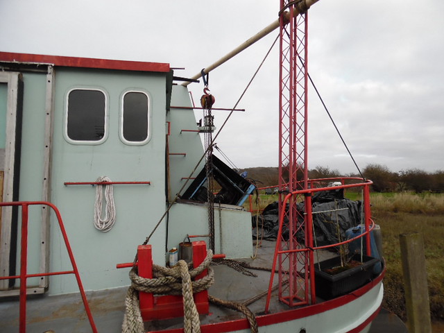 SAM_0167 SAM_0167 by mudlarker2, on Flickr |
|
|
|
Post by Telemachus on Mar 3, 2019 12:06:21 GMT
It is only called an earth strap by people who don’t know what they are talking about. Quite a few of them around, I’ll grant you. your reference please Engine casing covers all the bits encasing the moving parts of the engine, eg block, head, crankcase, accessory drives etc. Sorry if you haven’t heard the term before other than in reference to commercial vessels, but I guess your experience outside that tiny sphere is very limited. The engine casing is in effect the engine room and covers ventilation shafts etc that are the integral part of it. as reference I direct you to forshipbuilding.com/ship-construction/engine-room/this is a picture of a generator being lowered through a hatch in the engine casing of Sabina SAM_0167 by mudlarker2, on Flickr I’m not disputing that the term “engine casing” has a specific meaning in the context of large commercial vessels. But I would point out that we are not talking about large commercial vessels. Try typing “engine casing” into google, select images, and see what comes up. Ooh look, it is lots of pictures of bits of engines, what a surprise! |
|
|
|
Post by JohnV on Mar 3, 2019 12:20:22 GMT
I’m not disputing that the term “engine casing” has a specific meaning in the context of large commercial vessels. But I would point out that we are not talking about large commercial vessels. Try typing “engine casing” into google, select images, and see what comes up. Ooh look, it is lots of pictures of bits of engines, what a surprise! You demand precise terminology in electrical matters, fair enough, though I think your insistence on minutiae often obscures the important points trying to be put over. We are talking about marine installations therefore the precise terminology should be used there as well. Failure to do so and to accept when you are corrected does not reflect very well. |
|
|
|
Post by Telemachus on Mar 3, 2019 12:31:55 GMT
I’m not disputing that the term “engine casing” has a specific meaning in the context of large commercial vessels. But I would point out that we are not talking about large commercial vessels. Try typing “engine casing” into google, select images, and see what comes up. Ooh look, it is lots of pictures of bits of engines, what a surprise! You demand precise terminology in electrical matters, fair enough, though I think your insistence on minutiae often obscures the important points trying to be put over. We are talking about marine installations therefore the precise terminology should be used there as well. Failure to do so and to accept when you are corrected does not reflect very well. There is no point in applying what you consider to be “precise terminology” completely out of context. We do not have “engine casings” in leisure canal boats (which is what we were talking about), we may have “engine rooms” but that’s about it. If we are ever talking about your boat I shall try to remember to use the correct terminology for a large commercial vessel. But since I know very little about such vessels, it’s unlikely I will have anything helpful to say. |
|
|
|
Post by JohnV on Mar 3, 2019 12:36:44 GMT
the engine room is an engine casing
Nick, you need to learn to quit when you are ahead
|
|